John’s Repair Guide to an ETX-70AT
By John Cooney
Preface:
I want to
start by saying; I am not a professional repairman nor an
English major. I am a High Energy Physics major turned video game
developer who still loves to gleefully gaze deep into the glories of the
heavens. What you are about to read is my experience with a Meade ETX-70AT I
purchased on Ebay. When I won the auction I was
elated that I got the scope so cheap. $175 for the scope,
tripod, hard case, flexible focuser oculars, Meade electric eyepiece, compass
and level. WOW, that was a lot of stuff. When the scope arrived I
quickly opened it up to find the focuser pushed all the way out of the scope
and both clutches not engaging. My heart
sank. Quickly I called the guy I purchased the scope from; I got his machine so
I left a message. Thinking that I would never hear from him, I started on the
repairs you will find below. A few days later the gentleman called me back. He
was shocked that the scope was damaged. He explained that he had sold the scope
once before and shipped it, but it was returned because the first purchaser was
not satisfied. After his immediate offer to refund my money I realize he was on
the level. I realized he had no hope of repairing the scope and would only be
stuck with a broken scope. With this I told him it was totally ok, that I had
the ability to fix it, and I would keep the scope. Honestly I needed something
to do; I was stuck in LA far from my
Focuser repair note:
If you don’t
want to, or are not comfortable completely disassembling your scope but need to
repair a focusing shaft pushed through the plastic, skip to section DD and I recommend
you use the 1/8” X 1” fender washer cut to fit the scope. The larger surface
area will provide a better bond for the epoxy. This method only has a washer on
the outside of the scope, wile this will fix the problem, you do have a bit
more “slop” in the focuser compared to the complete fix.
Equipment:
To start
find a sacrificial white towel to work on. This is an excellent surface to keep
small screw from rolling around and dropped parts from bouncing off the hard
table top. Also, I like to wipe my fingers on the edge… but that is not very
professional, but again I never claimed to be that. Next, bright lights, some
music and the list of stuff below all of which cost me less than $15 to buy and
Home Depot, including tools.
1)
medium philips screwdriver
2)
5/64 allen wrench
3)
very small standard (flat) screwdriver
4)
side cutters
5)
Very small allen wrench to
remove focus knob
6)
medium grit sandpaper
7)
cotton balls
8)
q-tips
9)
mineral spirits
10)
white lithium grease
11)
1/8” X 1” fender washer (focuser repair/ tune up
*optional see below)
12)
#6 flat cut washer (focuser repair/ tune up)
13)
“Plastic-Fusion” Epox glue (focuser
repair/ tune up)
The Damage:
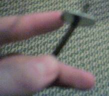
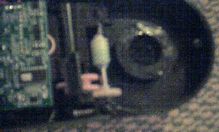
Let me
begin by apologizing about the very very poor picture
quality. I was using a digital camera that did not have a preview window and
had no idea the pictures turned out this horrible until after the job was done.
But they serve the purpose and next time I disassemble the scope to modify the
baffles I will take new pictures. So on to the damage.
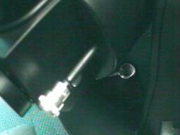
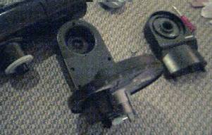
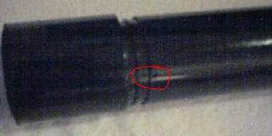
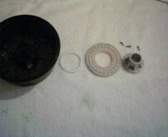
Ouch!!!
From what I
can tell the scope must have been dropped on the objective lens shoving the
focus shaft out of the OTA. The “step” in the rod broke out the plastic thus
creating a situation where the focuser would not function. In short, it punched
a hole right out of the plastic back. **The focuser on the ETX 60/70AT work by
moving the objective lens in and out on a threaded shaft. The focusing rod has
a “step” (the rod has a slightly smaller diameter at the end allowing it to fit
through the hole only about ½ inch) on the end of the
rod that stick out and the focusing knob is attached. When you focus out the “step” presses on the
plastic inside the scope moving the objective lens away from the knob. Focusing
in causes the knob to be pulled to towards the objective lens until it presses
against the plastic outside the scope then pulling the lens in. The “slop” in
the focuser is caused by the small gap between the knob, plastic, and “step” on
the rod. **
The Fixing:
As a note to remember, the scope comes apart and goes back
together very easily. If you find yourself having to put ANY force on the scope (other
than where I make a note) you will probably break something. If you find it
difficult to assemble, STOP, LOOK, then try again. If you are still stumped
e-mail me and I will walk you through it, and possible even call you to help.
Forcing the plastic bits will only cause damage, and that sucks. Please read
all the steps before you begin this. You should read 3 steps ahead when working
as good practice.
a)
Start by removing the focusing knob.
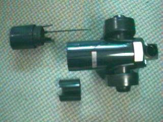
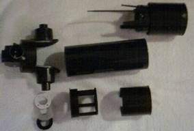
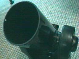
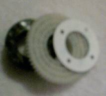
b)
Gently pull on the objective lens assembly. The entire
assembly should slide out as seen above. If the focuser rod was shoved out as
mine was, it might take a LITTLE pressure to slide it out.
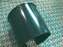
c)
Remove the friction sleeve from inside the OTA. (below the
scope in picture above)
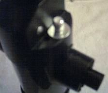
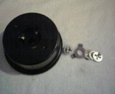
d)
Flip the scope over and pop off the access plate in the
middle of the drive base
e)
Remove the “clutch nut” from the locking lever shaft.
Using a small screwdriver to help make the first turn eases the removal
f)
Remove the clutch assembly and set it aside in a clean
area
g)
Gently pull the base away from the scope, it will slide
off the center shaft once cleared from the drive gear
h) Set the 2 nylon bushings aside
i)
Remove the 3 large Phillips screws located opposite the
drive motor. These screw hold the left (looking down on the scope with the
objective lens pointing away from you) support arm in place.
j)
Remove the left locking “nut” on the outside of the
support arm. It has the Meade star on it and a plate with numbers. It will spin
off.
k)
Loosen the right locking “nut” on the outside of the
support arm. Once you begin to loosen this nut the scope will begin to shift.
Do not completely remove the nut yet.
l)
You should now have more than enough play to slide the
left support out and set it aside. Finish removing the right nut and set it and
the drive base aside.
m) Remove the gear clutch plate and pressure bushing off the right side of the scope and set them aside.
n) Remove the 2 Philips screws located under the mounting shaft on each side of the OTA.
o) Remove the 4 allen screws on the back of the OTA on either side of the eyepiece holder. (one screw is used to hold the finder scope in place, but remove it anyway)
p) Slide the eyepiece holder assembly (black) off the OTA (blue) and set aside.
q) OPTIONAL. Remove the 3 Philips screws from around the back of the OTA to slide the baffles out. Do this only if you want to cover them with felt or do additional light dampening inside the tube.
r) Take a #6 washer and make sure it stops on the “step” of the focusing shaft. Do the same with a fender washer.
s) TEST FIT!! Put a #6 washer on the focuser shaft then slide it into its hole on the eyepiece holder. Make sure you have enough room to attach the focusing knob.
t) TEST IT AGAIN!! Be sure you are fitting the correct hole. It should be the center hole (between 2 others) on the left side looking into the assembly.
u) Epoxy the #6 washer inside the eyepiece holder assembly. Clean up any extra epoxy. Let dry!!
v) Apply a small amount of lithium grease to the washer.
w) Follow steps n-q in reverse order to replace the eyepiece holder.
x) Apply a THIN layer of lithium grease to the inside of the friction sleeve. This will allow the focuser to move smoothly and have constant “load” from the grease. My focus performance is smooth and easy compared to a new 70AT.
y) Clean the old grease off the threads on the focuser shaft with mineral spirits, dry and apply a thin layer of lithium grease. IMPORTANT, run the shaft in and out several times and remove any extra grease as you don’t want it falling in and hitting the objective lens.
z) Match the friction sleeve to the objective lens assembly. You will notice a guide notch only allows it to fit in one position. Make sure the collar on the sleeve is facing towards lens.
aa) With the collar held about ½ way on the lens assembly line up the notch on the outside of the friction sleeve with the hole on the OTA. Slide assembly together.
bb) You will need to press the friction ring into the OTA making the little notch pop into the hole on the OTA before you push the lens down into position.
cc) Slide the objective lens all the way down the OTA. You might need to wiggle the lens a bit to get the shaft to come out the back of the eyepiece holder assembly.
dd) Here we have a couple of options. You can use another #6 washer on the outside of the assembly to remove the “slop” in the focuser. I found that the #6 was too thin and wanted a thicker washer. I found a 1/8” X 1 fender washer was the perfect thickness but was a bit too large. I cut one side down with a pair of side cutters and sanded it smooth. This also provides another layer of protection from the shaft being shoved out again. Test fit the outside washer with the knob attached before you epoxy it in place. When you are ready to glue, just slide the lens back a little bit to pull the shaft inside the OTA. Once dried slide the lens back, guide the shaft through the hole and attach the focusing knob. Set the OTA aside.

ee) CLEAN CLEAN CLEAN!! Next carefully remove all the old grease from the scope and support braces. Use the mineral spirits and cotton balls to clean them up nice, then dry it completely. I did not clean the small gears on the drive motors. They are delicate and difficult to get to, unless you are brave and have a steady hand I would let the stock grease to the job.
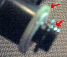
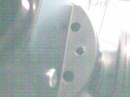
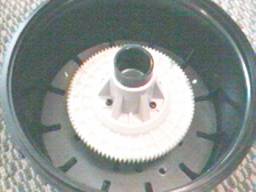
ff) Sand both sides of the white nylon clutch bushing. Make sure it is free from grease. Apply a small amount of lithium grease to the teeth of the OTA gear then slide it onto the right OTA shaft followed by the clutch plate and black plastic bushing. The bushing has a guide notch and only fits in one way. Apply a small amount of grease to the outside of the bushing. Only the areas pointed to in red above should have any grease on them, this is very important if you want your scope to track accurately.
gg) Apply a small amount of grease to the worm gear inside the right support brace, and then replace the cover plate and 5 screws.
hh) Remove the bushing on the left riser brace, clean it, and reapply new lithium grease. Make note of the 3 plastic pins that match up to the holes on the left side of the OTA.
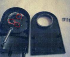
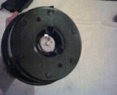
ii) Replace the OTA into the right brace, loosely threading on the right “nut” to hold the OTA in place. Take note to align the left side brace properly to the OTA. The pins (circled in red) on the left bushing must line up with the holes on the OTA if the stops are going to work properly. Rotate the left brace into its original position and replace the left “nut” snugly. Snug up the right nut, and then replace the 3 large screws that hold the left brace in place from below the scope base. Set upper assembly aside.
jj) Pick up the lower base, remove the 3 screws holding the large gear and clutch plate in place.
kk) Sand both sides of the clutch plate and degrease the drive gear. Reassemble and apply grease only to the outside teeth.
ll) Apply a small amount of grease to the worm gear under the base. Apply a small amount of grease to the metal shaft, and then replace one of the nylon bushings.
mm) Carefully slide the lower base into the upper assembly. Be careful to make sure the lower drive assembly is all the way back. It is spring loaded to keep it engaged to the large gear. I angled the base slightly towards the drive assembly and wiggled the base down without any force. It might take a couple tries, but DON’T FORCE IT, it will break, and you will be in real trouble. Once in place insert the lower nylon bushing, it will wiggle into place.
nn) Replacing the lower clutch assembly is an art in of itself. The mechanics to do this are simple. Hold the scope over your head; place the assembly in place making sure the plastic prongs are sticking through the round nut. Begin to thread the nut into place. Once you run it up snug you can flip the scope over and take down from over you head. The reason for the acrobatics are to keep the dual threading lined up somewhat closely. You will notice the inner plastic bit is also threaded and needs to line up with the big round nut. The easiest way to do this is hold it over your head and thread it up using gravity to keep the plastic nut in contact with the round metal nut.
oo) The art of the lower clutch. The nut needs to be tight enough to lock when the locking lever is pushed towards the plastic notch, but loose enough to move the scope when it is in the opposite position. I found after a few different tightness adjustments a comfortable middle ground was found. Replace the lower cover and clean up.
pp) Plug in your Autostar and give the scope a give your scope a new slew test drive. I found mine moved much smother than the unmodified new 70AT I tested against.
Closing:
If for what ever reason you have any questions about the process described above, please feel free to email me. I will do my best to help answer any questions you have. Soon I will have my review of accessories and photos I have taken with my 70AT. Thanks for reading this, and if you have found this useful drop me a line so I know my rambling have not fallen on def ears. Thanks!
John Cooney