TECHNICAL TIPS
Last updated: 16 January 2001
TECHNICAL TIPS |
I wrote to you about a week and a half ago about the electric focuser being too fast. I've since modified mine and improved the performance on slow speed significantly. I've documented the modification below. Because the modification is quite fiddly, I've included a reasonable amount of detail - hope you don't think it's too much.
ETX-90 Electric refocuser modification to reduce focus speed
Note: This modification should only be attempted by persons who are confidently competent at soldering very small circuits. Without care and skill, damage to your focuser is almost inevitable. If you don't think you're up to this mod, seek assistance from a more experienced hobbyist. In any case, read and understand the procedure thoroughly before you commence.
Introduction
I have been using the electric focuser for a few months now and am very happy with its ability to simplify focusing without shaking the sky. My one complaint however is with the setting of the focus speeds. Although the electric focuser boasts four speeds, I have found that they are all sufficiently similar to each other that I only ever make use of the fastest and slowest. Even more annoying, the slowest speed is way to fast to deserve its name of "fine".
Because the slowest focusing speed is still too fast, the only way I have found to successfully use the focuser is to become adept at pressing the focuser control buttons for the briefest duration my fingers can manage. Unfortunately for me, just the slightest of taps is still enough to set the focuser motor in quick motion and before I've realised, I've already passed the point where I wanted to set it. Perhaps some of you have also experienced this annoyance too.
Finally, I could bear it no longer. My hacker curiosity got the better of me (as it always does) and I opened the focuser to take a look at what made it tick. After some experimenting, I was able to slow the focusing speed down by 50% or more and my friendship with my electric focuser has improved significantly.
The circuit diagram
While it's not necessary that you look at or understand the circuit before you carry out the modification, many of you are likely to be interested anyway. Here is the circuit of the unmodified electric focuser as best as I could determine. (click to enlarge the image for printing).
As you can see, the circuit is relatively simple but there are a couple of noteworthy points.
The heart of the circuit is U1, a PIC microcontroller. It is responsible for generating a PWM control signal to regulate the speed of the motor and is programmed during the manufacturing phase of the electric focuser. If you don't own a Meade electric focuser and are thinking that you'd like to use my circuit diagram as a basis for your own home brew version, think again. You'd need to write a PIC programme to emulate Meade's implementation and I haven't provided nearly enough information in this posting to allow you do this. I trust that this keeps Meade satisfied that electric focuser sales won't be harmed.
The wires from the coiled interconnecting cable from the ETX base arrive at the left of the diagram and are labelled by their colour. I don't know why by on my unit, Meade has used the red wire for the negative power input and the black wire for positive. The blue and yellow wires carry the IIC control link.
The actual motor drive circuit is a classical H-bridge design and consists of FETs Q1 and Q2 and NPN transistors Q3 and Q4. The job of the PIC is to drive the H-bridge with a PWM (Pulse Width Modulation) waveform to make the motor change its speed and to turn one direction or the other.
The idea behind PWM is that instead of simply applying a steady voltage to a motor and letting it run, you very quickly apply the voltage, turn it off again, then turn it on, off, on, off etc - more or less how a household light dimmer works. If you have it turned on for longer than you have it turned off, then the motor will turn faster. On the other hand, if you have it turned off more than on, it will turn slower.
The modification
The easiest and most convenient way to modify the ETX to have slowed down the speed of the "fine" setting would have been to change the software. Because the PWM control loop software is burned into the PIC, there was only a remote chance that this would be possible, and Dick Seymour's generous advice proved that Meade has not implemented the electric focuser in a way that this would be possible.
A hardware modification to the focuser is therefore the only feasible way of slowing it down. Although there are technically superior ways of slowing a PWM controlled motor, I chose to use a resistor in series with the focusing motor - it was an easier mod in the space available.
Making the modification
Before you actually open your electric focuser, read my message at the top of this page and think about it. If you can honestly look at yourself in the mirror and say "I am a competent solderer and I can fix electrical things when I break them", continue. Otherwise, I'd recommend you pull out your phone book of contact names and find a competent friend.

The tools you'll need include
You'll also need to obtain 4 cm of ribbon cable (like the ribbon cable used for printers or serial connections) and a 22 Ohm quarter watt resistor.
I tried several resistors between 22 and 33 Ohm. The down side of choosing a higher valued resistor is that as your batteries become less and less charged, you'll reach a point where the slowest speed on the focuser stops working. With a higher valued resistor, you reach this point sooner than you would have with a lower valued resistor.
I should comment that I use NiMH rechargable AA batteries in my ETX. These have a regular voltage output of between about 1.25 and 1.35 Volt. If you use normal Alkaline cells, the voltage output is a little higher and you may need to choose a slightly higher valued resistor. If you use NiCd batteries, the voltage output is a little lower and you may need to choose a lower valued resistor or forget this modification all together. I'll leave it to your judgement and experimentation - perhaps you can provide some feedback.
Remove the electric focuser body from the ETX and open it being careful not to lose the two screws. You'll find that the printed circuit board is "tied" to the housing with very short wires that make it difficult to remove the printed circuit board. You may, like me, break one or more wires away from the printed circuit board when you try to take the PCB out.
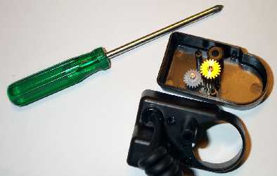
In this photo, you can't see the printed circuit board because it is hidden underneath the lower base cover. The two gear wheels you can see in the upper base cover are loose. If you turn the cover upside down, they'll fall out. Be careful not to lose them.
The next step is to repair any wire damage you might have caused in opening your unit. This is what the ribbon cable is for. By adding the ribbon cable, you will also obtain some extra room to work with when you're adding the resistor.
You should carefully desolder the six flying wires that tether the PCB to the plastic focuser base and clean out the six through holes on the PCB where the wires originally were. But before you remove the first wire, scribble yourself a simple diagram so that you know which coloured wire went where!
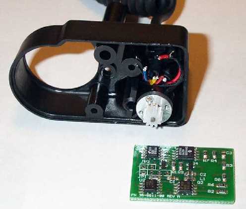
The desoldered printed circuit board now looks like the photo above. Here, you can see how short the flying wires really are - they barely extend past the lip of the plastic base. Also, on the printed circuit board itself you can see where the wires came from - the two hole and four hole white rectangles at the mid left of the board.
When you desolder components, you normally end up with some flux residue on the PCB. Isopropyl alcohol is a common fluid that will usually remove solder flux.
The next step is to prepare the lengths of ribbon cable. You'll need a short length of 4 conductor cable for the connection to the ETX base and another short length of 2 conductor cable to connect to the motor.
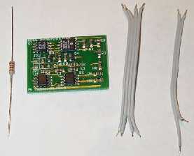
Here is a picture of the lengths of ribbon that I used, and I'll tell you that I should have made them just a little shorter. Although the wires in this picture are a little longer, 4cm would be a good length as I mentioned above. You'll notice that the lower end of my length of 2 conductor ribbon has been stripped back a little further and one of the conductors has been chopped short. This is to accommodate the resistor.
Carefully strip a 1 mm section of plastic insulation of each of the conductors, gently twist the strands of wire in your fingers so that each exposed end forms a tight straight bunch. Then tin the wires with barely enough solder. If you do this right, you should find it difficult to tell whether the wires have solder on them or not (the wires in the picture have already been tinned with solder but you can't tell by looking at them).
The next step is to insert the resistor. The resistor is going to be connected in series with one of the motor wires . The motor wires were originally connected to the rectangle with two holes in it. It doesn't matter which of the two holes you put the resistor into and you'll see below that I chose the hole that was closer to the middle of the PCB.
[Note: if you're not sure what value of resistor to use, you can temporarily connect short thin wires to take the motor connections outside the focuser housing. You can then reassemble the focuser and attach it to your ETX to experiment with different values of resistor to see which works best for you. I used wire wrap wire to do this experimentation. You do need to check resistance values with the focuser attached to the telescope - the mechanical load that the telescope places on the motor is significant and you'll find that the speed that the motor turns will be different when attached and not attached to the telescope.]
Mount the resistor radially - meaning, only solder one of the resistor's wires to the printed circuit board and leave the resistor sticking up into the air like a high rise tower. When you solder the resistor to the board, make sure that the resistor isn't pulled down so close to the PCB that it is tight. You need to leave some slack because you need to be able to bend the resistor around just a little when you reassemble the focuser.

In this photo, you can see the resistor mounted radially and it's top wire cut short to about 1mm from the resistor's body. You should now connect the shortened wire to the flying end of the resistor as shown in the photo.
Remember that simple diagram you made earlier showing which coloured wire went to which hole? Now is when you're going to use it.
Carefully clean up the ends of the original coloured wires from the motor and the ETX base and trim them to about 1mm using the wire cutters. You can now solder them end to end with the ribbon cables being very careful to make sure that the right colour goes to the right ribbon wire to take it to the right location on the PCB.
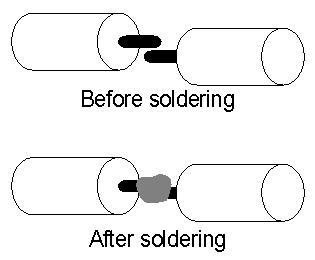
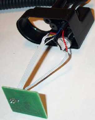
This is what I mean by soldering the wires together end to end.
Now the only thing left to do is to insulate the exposed solder connections to stop them shorting with each other. I needed to "invent" a new way of insulating wires that did not take up a lot of room - because it's squeezy getting everything back into the focuser now that there's some extra wire and a resistor. I decided to try to use hot glue to insulate the exposed wire and was very happy with the results.
Before you start to squirt hot glue, get your glue gun to a good hot temperature so that the glue is flowing freely. Then, using your fingers, arrange the pair of motor wire connections close to each other (say about 1 mm apart). Carefully, ease just enough hot glue onto the front and back of each of the two solder connections as to completely surround the connection. I also glued each of the insulated wires together to make one tight ball. The hot glue or the tip of the glue gun itself can burn you and so you need to concentrate and take your time.
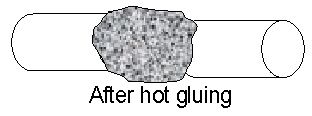
The finished product should be a glob of solid hot glue that's ball shaped and a few mm in diameter. It should envelope the solder joints and just a little of the plastic insulation of each of the wires as shown below (only one wire shown but you can imagine a group of these stuck together - there's a photo below too).
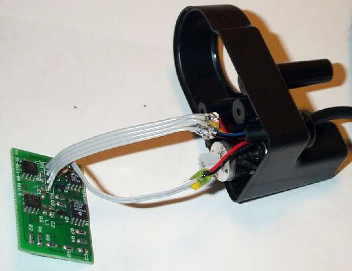
In this last picture, you can see the efforts of my hot gluing. The lower wires, the motor wires, show a little yellow/greenish blob where the hot glued insulation is because I used some electrical tape between them. I found that the tape was unnecessary and so I didn't use tape in the ETX base group of connections.
Now that all of the construction work is done, you can take some time to very carefully double check all of your wiring. Remember, if you got it wrong, your expensive focuser might fry itself when you power it on.
To satisfy yourself that it all works before you reassemble it, you can leave it in its opened state and connect the coiled cord to the base of your ETX along with your Autostar. Make sure that there are no metallic objects or exposed wires anywhere near the exposed focuser so that there's no chance of something inadvertently making a short circuit.
When you power everything on and your Autostar completes its initialisation, you can try to use the focus controls to see that everything is OK. If your fine speed no longer appears to work but the slow, medium and fast do work, then your batteries are a little low in voltage or you've chosen too high a valued resistor.
If none of the speeds work, remember what I said when I suggested that you double check your wiring?? Hope that you didn't mess up too badly and go find the problem.
When you reassemble the focuser, be careful to keep the ribbon cables from fouling the moving parts. You might need to use your needle nosed pliers to carefully jiggle the ribbon into the available space.
If you're having trouble getting your focuser cover onto your base, make sure that the PCB is seated correctly inside the almost invisible plastic guides. If you can't get your PCB to sit vertically, you may need to trim the solder connections to the wires and the resistor at the underside of the PCB so that the PCB can sit a little closer to the side of the focuser housing.
Congratulations, the focuser slow down modification is now finished. Clear skys and happy slower focusing.
Return to the top of this page.
Go back to the Tech Tips page.
Go back to the ETX Home Page.