ETX TECHNICAL TIPS
Last updated: 7 February 2001
ETX TECHNICAL TIPS |
THE ULTIMATE PIER AND WEDGE ASSEMBLY FOR THE ETX 125
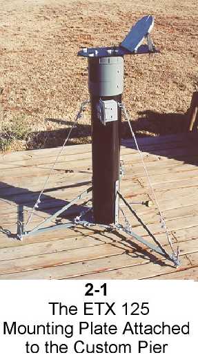
This photograph shows the completed project in which I was able to design an effective, cost-efficient, and very stable supporting assembly for the ETX 125. Using the moderately heavy (and expensive) instrument, I realized early that the Deluxe Field Tripod #883 should not be offered even as an alternative to this telescope. Although it WILL support the ETX 125 in Alt-Azimuth mounting, it is precarious even in that postion; on the other hand, in POLAR mounting, where the telescope assembly is tilted to the observer's latitude, the telescope is very, very easy to tip over in either a northwest or northeast (northern hemisphere operation) direction.
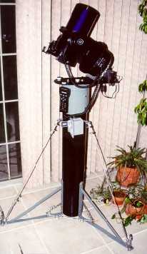
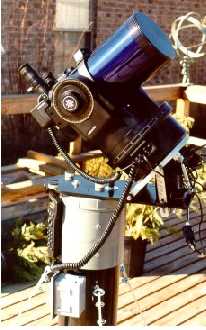
For field work in remote and dark locations, I now use the Meade model #887 Heavy Duty tripod and wedge, but for my observing deck behind my home I have designed and built the transportable pier and combination ALT-AZIMUTH / POLAR observing platform, complete with slow motions for accurate alignment and functional power outlets, accessory holders and leveling screws. Two identical assemblies were built; the prototype is shown (it took the bruising from many changes and adaptations as the process went along!) and the other is available for purchase to anyone wishing the best in observing solidity and comfort.
Although somewhat resembling others that have been similarly designed, this design offers the very finest in observing ease and absolute maximum strength.
PART 1 - Construction of the Pier
Every observer constructing his or her personal observing pier (and many people do just that rather than accepting what is available "off-the-shelf"), should first determine the most comfortable height for them and decide if that pier should be constructed for either 1) standing without stooping; or 2) sitting. I prefer to stand, and for my height, a pier of 42 inches above the ground was ideal. The wedge (Polar) adds another six inches which brings it to my eye level for about 70% of the sky. For this design, whether used in Polar or Alt-Azimuth, the eyepiece is conveniently always located at the same relative height.
The list of materials for the PIER (only) is: (available at Lowe's or Home Depot)
1) PVC sewer piping, 36" long by 6-1/2" o.d., cut perfectly square on both ends;
2) Three (3) heavy steel legs (I converted three INDUSTRIAL SHELF BRACKETS), of 1/4" thick by 1.5" wide, with a leg length of 19" and bracket (to attach to the pier) length of 13"; the nice thing about the industrial shelf brackets is that they come PRE-DRILLED in almost exactly the right places with 1/4-20 holes; it was necessary for me to drill only three (3) holes in these brackets, one on each leg end (3/8" hole) for the leg leveling bolts;
3) One (1) PVC 6" sewer pipe connector (has two female ends, one which inserts over the pier top and the other connects to the....:
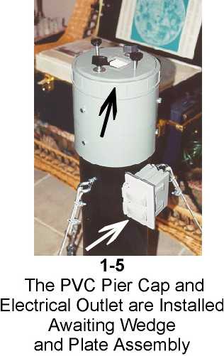
4) One (1) PVC 6" clean-out cap screwed and cemented into a 6" adapter which, in turn, is cemented into the top of the pipe connector (#3) to form a base on which to bolt the mounting plate (the clean-out comes with a square wrench extension - sort of like an extruding "box" - in the middle which MUST BE SAWED OFF with a hacksaw (you can see the remaining hole in Photo 1-5); once it is sawed off it is VERY important to use a wood plane or file to obtain a perfectly flat surface.
5) Three (3) 1/4" stainless turnbuckles to provide tension on the torqueing cables between the pier top and the legs (Photo 1-4);
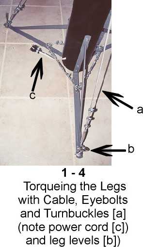
6) Three (3) 3-foot long plastic coated strips of 1/8" cable, with six "U" fasteners per cable to secure the turnbuckles and eyebolts;
7) Six (6) 5/16" x 1.5 inch long eye bolts to secure the cable (three for the top of the pier and three for the legs);
8) Three (3) 3/8" x 4" long stainless eye bolts for leveling;
9) Nuts, bolts, and lock screws for everything listed above;
10) A three-foot length of Romex electrical wire;
11) An outdoor plug box, plug and plate for electricity;
12) A small piece of standard flooring linoleum.
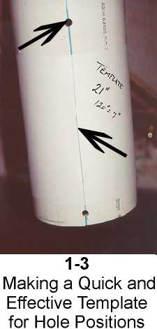
After squaring each end of the 6" pipe, carefully make a center line from top to bottom as your starting point; make a template out of 22" long paper, make marks at each 120-degree position (measure the paper flat first with a ruler and divide and MARK into three equal lengths of a little more than 7" each) then roll paper around the tube, tape the ends of the paper together and align with your center line (Photo 1-3). This sliding template serves as a marker for every drill hole that must be made to secure the hardware to the pier.
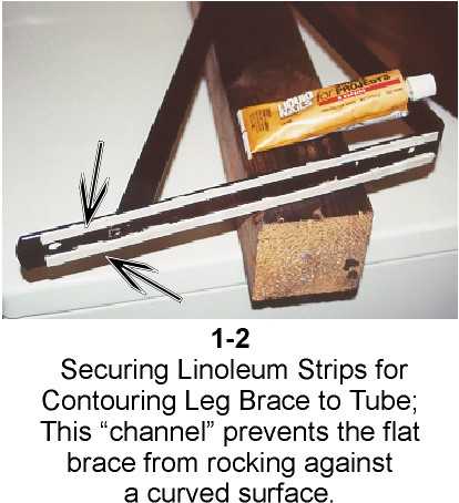
Before priming and painting legs, use Loctite permanent glue or Liquid Nails to fasten (Photo 1-2) 1/4" strips of linoleum the entire length of BOTH sides of each brace that will attach to the curved pier; this will GREATLY minimize "rocking" of the flat leg against the curved pier once the leg is secured; if you do not do this, you may as well not even finish the pier! I used stainless 1/4-20 one-inch long bolts (three per leg) combined with locking washers and nuts attached on the inside of the tube.
Regarding the legs, be sure to START AT THE NORTH side of your PVC tube; my center line (Photo 1-3) also served as my "north marker." You MUST place one leg exactly on that line for the maximum stability when tilting a fork-mounted scope into Polar position! All other legs are placed 120 degrees RELATIVE TO THAT ONE!!
At this point, if you want electricity at your fingertips as shown, merely drill two (2) 3/8" holes to slip the Romex wire through, one at the top where you plan to attach the receptacle box (use two 10 x 32, 1" bolts w/locking washers through the pier) and one at the bottom SOUTH side of the pier. If located South and at the bottom, you will have considerably less worry with cords getting in the way in the dark.
Prior to placing the connector and end cap on, if you have drilled 3/8" holes for it, you can run the Romex wire down through the pier (mine comes out the back, or South), extruding through the bottom for a power plug; at the top, the wire should come out (mine is West to correspond with the control panel on the ETX) and enter a receptacle box and plug that is fastened to the pier with small bolts and nuts. This is shown by the white arrow in Photo 1-5. Having the electricity right at the telescope is an absolutely wonderful luxury; I have even wired through the box a small red reading light and switch atop the wedge assembly.
Now, once all holes are drilled, prime and paint all components thoroughly; I used four (4) coats of light Rustoleum primer and then four (4) coats of semi-gloss paint of selected colors. After the entire unit was assembled, I painted EVERYTHING (bolts, nuts, turnbuckles, PVC....) with three good coats of clear polyurethane for added protection, since this unit will be left outdoors when not in use.
Slip 6" connector over TOP of pier and apply PVC cement just before in position (you will have drilled holes to secure; I tapped mine for 1/4-20 bolts seen in Photo 1-5). Once connector is secure, tap into place and also bolt down the Clean-out plate with its adapter as your top plate.
NOTE: You can see that in these initial photos, I had used tension cable and turnbuckles BETWEEN each leg to prevent spreading, much like you should do between the pier top and the end of each leg (Photo 1-4); after assembly, it was found that the cable between the legs DID NOT prevent leg motion and hence, this assembly was replaced with 1/4" thick x 1" wide aluminum bars that were bolted between each leg. The "inter-leg" braces are ABSOLUTELY NECESSARY for maximum stability and minimal vibration! The pier and mounting combination is now rock-solid with this arrangement.
Fasten and torque the coated cable wires from each leg end to the eye bolts atop the pier; CAREFUL!! DO NOT tighten the cable so much as to bend the leg ends!
TOTAL WEIGHT OF UNIT, LESS SCOPE AND WEDGE - 32 pounds.
TIME TO CONSTRUCT (off and on, total hours) - 16 hours (not counting paint drying time!)
You are now ready to design the perfect mounting/wedge assembly for your ETX telescope!
PART 2 - The Ultimate ETX Mounting Platform
The telescope is only as good as the mounting; we have seen how to provide the most stable portable support possible for the ETX 125. If the telescope was always going to be used in the Alt-Azimuth mode, as many ETX-ers prefer, it would be a simple matter to at this point to attach a plate under which your hands could secure the base of the scope tightly into place. I frequently use my ETX in Alt-Azimuth mode so this platform has been designed for quick attachment in EITHER MODE!
However, I prefer by a long shot to operate my ETX 125 in a POLAR position because it tracks and slews better and seems to operate more efficiently in all aspects, including reductions of "creeping" and random slewing. Large portable tripods provide Polar mode via a "wedge assembly" which tilts the fork tines of the mounting toward the North Celestial Pole (or your latitude toward the star Polaris).
When tilted in such a way, the center of gravity of the entire telescope assembly MUST be over the pier or tripod, and the tilting mechanism MUST be rock solid once your angle is set.
The combination mounting platform/equatorial wedge system which I designed is seen in Photos 2-1 through 2-6. For the prototypes, I had a local tool design and machining company handle the first-class machining since I wanted perfection on the first units.
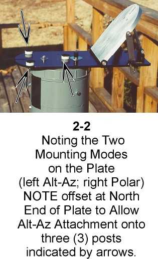
The mounting platform provides TWO observing capabilities: 1) the front of the platform (see Photo 2-2 arrows) provides a remarkably stable flat platform on which the ETX can be mounted in Alt-Asimuth orientation. The Alt-Azimuth mounting area is located on the NORTH end of the assembly. As can be seen, the telescope rests on three (3) teflon plugs (1.25" diameter and 1/2" thick covered with felt). In the same figure you can see the SLOTTED guide for the 1/4-20 hand bolt which secures the base in Home Position. This allows you (just as with the tilting wedge plate (Figure 2-6)) to engage the bolt PRIOR to setting on the mounting plate, slip the scope into position via the slot, and then tighten. Thus, there is no risk or danger of dropping the telescope when installing.
Regarding firmness, vibration and stability: if you are going for maximum steadiness, the TAKE OFF THE RUBBER FEET from the base of your ETX; sure, these "grip" a surface to keep the base from rotating, and I suppose prevent scratching of furniture, but they are so soft that they introduce considerable "wobble" no matter WHAT you mount your scope to!
Once firmly attached, this platform for Alt-Azimuth operation is solid and vibration-free, far superior to any tripod I have used.
Fine adjustments for tweeking to home position in azimuth are discussed momentarily.
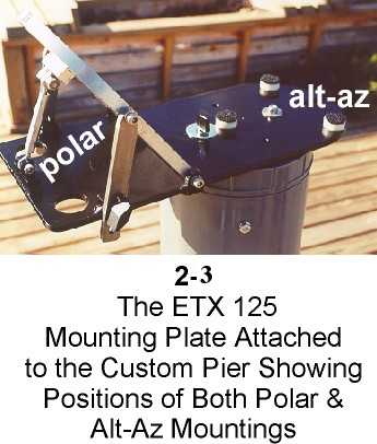
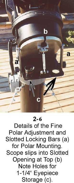
The second mode which this mounting platform allows is POLAR (see Photo 2-3); this is accomplished by a moveable (in altitude) 1/2" aluminum plate supported by two slotted stainless steel (5/16" thick) bars. Note that these bars pivot on stainless steel allen bolts with lock washers; teflon spacers are used between every connection to completely remove any play in the system. The base of the tilting aluminum plate is similarly mounted to the plate. Both Photo 2-3 and 2-6 demonstrate the simple turnbuckle assembly used to fine-adjust the plate for precise elevation (latitude) to reach polar position; once alignment is achieved, the turnbuckle is totally taken "out of the equation," since it has inherent slop. Rather, the heavy bars are secured tightly in place to firm up all support of the base and the telescope.
In Photo 2-2, you can once again see another "hands-free" slot which is used for you to ease the scope down into position with the 1/4-20 bolt already inserted securely in the scope's base; once in position, the second bolt is fitted into place.
Eyepiece holes (1-1/4" i.d.) can be seen in both Photos 2-3 and 2-6.
AZIMUITH adjustment is necessary in BOTH Polar and Alt-Azimuth modes of operation. Looking carefully at Photos 2-2 and 2-3, you can see the layout of the entire mounting assembly and note the the provision for AZIMUTH ADJUSTMENT. Such adjustment is necessary for BOTH Alt-Az and Polar modes of operation. At the front end (north, curved end) of the plate you will notice in addition to the two teflon supports a locking acorn nut with Fender washer. Unseen, but beneath the assembly (between the bottom of the plate and the top of the pier) is a VERY thin 3" diameter teflon washer that serves as a sort of "lubrication" on which the heavy plate can pivot.
The acorn nut is fastened very securely to an extruded 1/4-20 bolt from the pier, but not so tightly to inhibit azimuth movement. The washers assure a tight and non-moving fit. Now look toward the MIDDLE of the plate, next to the third teflon support, just to the right of where the arrow is pointing in Photo 2-2. There is a hand nut, locking washer and Fender washer which is affixed to another 1/4-20 bolt which extrudes from the top plate of the pier; the steel mounting plate is fitted with a slotted and curved opening at this position to allow the mounting assembly to PIVOT in azimuth on the front bolt (the acorn nut) and subsequently be tightened securely by the hand nut once proper azimuth is achieved.
Holes are drilled in the steel plate to accomodate extruding 1/4-20 bolts that have been threaded out of the top cap of the pier prior to securing it in place. These bolts and be seen in Photo 1-5.
The steel 1/4" thick base plate is 16 inches long and 7" wide, while the 1/2" thick aluminum polar tilting plate is 7" wide and 8" tall to accomodate the ETX 125 base. Total weight of this assembly, less telescope, is 14 pounds.
PART 3 - The Finished Product
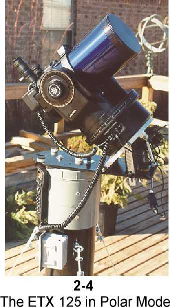
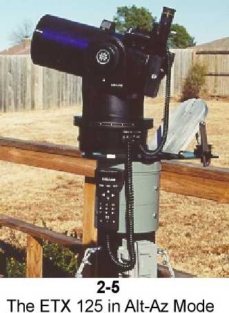
This series of photographs demonstrates the finished assembly and the versatility of such a configuration. Shown is my ETX 125 in Alt-Azimuth and Polar observing positions, to demonstrate that nothing "gets in the way" with either mode; indeed, while in Polar mode, the Alt-Az space allows a convenient accessory shelf!
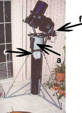
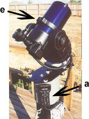
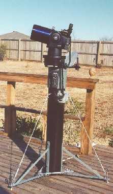
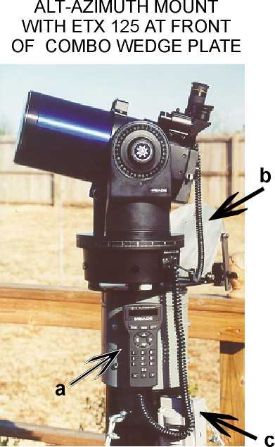
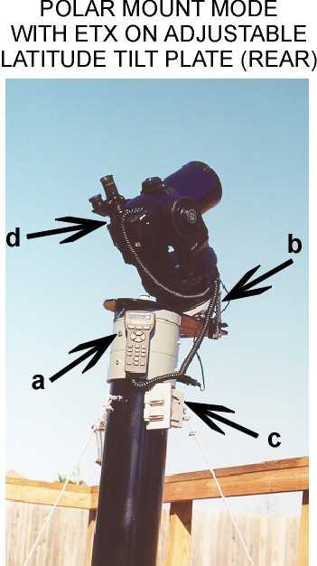
I have the Autostar and/or the standard electronic controlled fastened to the top of the pier with Velcro, and my AC converter plugs nicely into the top receptacle of the power box when in use.
Although this assembly is, indeed, portable the wedge and pier assembly combined weight nearly 50 pounds; the scope adds another 17 pounds to it. When using my new pier at home, I have a confined area of 6-foot high privacy fencing surrounding an 8 foot square observing deck (not shown). This fencing is to block stray light and gusty winds that are common here (we live within walking distance of the mighty Arkansas River). In this fenced flooring, I have provided cement supports totally SEPARATED from the deck (to minimize vibrations); the supports (3) come up through the floor to support each of the three legs. When in this position, the legs cannot move (they are restrained by small PVC tubes which hold tight on the leveling bolt tips) and the mounting plate, once aligned in azimuth, is firmly bolted into place with hand nuts through the threaded open holes seen in Photo 2-3 directly centered above the pier.
I can hit the pier very hard with my fist and all vibrations (as seen at 156x) die down in my field of view within 3 seconds, most of the vibrations being the "famous ones" from the plastic fork tines of the Meade mounting itself! In all honesty, without the telescope, there is NO residual vibration in the pier or mounting assembly whatsoever when locked tight.
There are many options and variations on this theme, but whatever any observer chooses should have the capability for many things; for example, even though I prefer the Polar alignment and use that nearly exclusively, there are times when I would like to track satellites with my ETX, something you can only do in Alt-Az mode. Likewise, there are MANY times when a friend or neighbor drops by and wants to peek at the moon or Saturn. For this, polar alignment and initialization is a waste of time....it is much easier and quicker to simply slip the telescope with its one bolt affixed right into place on the north end of the pier, do a quick "Easy" alignment, and be observing in a matter of seconds!
To that point and to close, the biggest advantage of this system is this: the pier and the metal mounting assembly lives outdoors. I built it to withstand the elements, and I put it outdoors and that's where it will stay. When the scope is NOT on the pier (never leave your scope out unprotected), I carefully cover the top of the pier (including the electrical receptacle) with a soft pillow case and then a very heavy plastic bag that reaches all the way to the feet. I DO NOT tie the bag tightly, but secure open at the bottom to the deck to allow air to circulate and minimize condensation.
Each evening I observe, I merely pick up my Meade ETX 125 (only 17 pounds of it) with one hand bolt attached in position, walk out to my observing station built onto my deck, and simply slip the telescope into which ever slot - Alt-Az or Polar - that I am in the mood for!
The power is already there (I have run an underground line to plug into), and I am ready to initialize. It doesn't get any better than this!
P. Clay Sherrod
Arkansas Sky Observatory
Conway / Petit Jean Mountain
Arkansas
Subject:	 Re: pier construction questions - from Weasner's site
From:	sherrodc@ipa.net (Clay Sherrod)
Glad your ETX 125 is performing well; they are great little scopes when
the do what they're supposed to.  I really like mine and am willing to
tolerate just about everything (which has, to say the least, been
diversified and mystifying) it throws my way.

Regarding the pier, I can see where Photo 1-5 might be confusion; I even
thought "...four bolts?" myself when you wrote.  There are two (2) round
hand screws (1/4-20) seen opposite one-another in this photograph (they
seem somewhat left-right in the picture).  Those two COME OUT of the
pier head; the top plate is threaded to accept them (they are bolts).
When I use the pier permanently from my observing deck at home, I keep
it aligned to celestial north so all I have to do is put the scope on
the wedge assembly.  When the pier is in its "home", I use those two
bolts to thread down firmly into the top of the pier to secure it
tightly; they really are not even needed, but I put them there in case.

If you insert the two bolts to permanently lock the wedge plate into
position, you CANNOT pivot the plate in azimuth for accurate star
alignment; so the bolts are for permanent installation only, and not
necessary if you plan on moving in and out of doors with it.  In other
words, to use as a portable pier, you DO NOT use those two bolts, as
this would prevent you from fine-adjusting in azimuth to line up with
the celestial pole.  Only the front thumb screw (it has a flattened
"bar" knob) is used to tightly lock the plate, while the rear acorn nut
and teflon washer allows the plate to tightly pivot to the desired
azimuth.

Thanks for writing; hope this clears up the "mystery bolts" and glad you
brought it to my attention.  I will probably save others the same
puzzlement!

Good skies!
P. Clay Sherrod
    -----Original Message-----
    Hello Clay,

    I hope you don't mind me e-mailing you personally but I would like
    to ask you a question about the construction of your pier. I have
    had a 125 for about a year a I have not had all the problems that
    others seem to have. I went from a 10" starfinder to the 125. Anyway
    my question. In your construction description photo 1-5 shows a
    close-up of the pier cap. There are four bolts shown, two are used
    to adjust the mounting plate. What are the other two used for? Am I
    missing the point somewhere? Any help you could give would be
    appreciated.

    Thank-you,

    Marvin
Return to the top of this page.
Go back to the Tech Tips page.
Go back to the ETX Home Page.