GUEST CONTRIBUTIONS ARCHIVE 1997
Last updated: 20 September 1998
GUEST CONTRIBUTIONS ARCHIVE 1997 |
Here are some miscellaneous contributions from other ETX users. If you have something that you think would benefit other ETX users please send it to me. Send any images as GIF or JPEG files; due to internet email gateway issues, please send only one image file per message. Send to etx@me.com. Alternatively, if there is a web page with the information please let me know and I'll include a link to it.
From: Paul J. Boudreaux (boudreau@eng.umd.edu)
After carefully following the discussions of the faulty operation of the R.A. drive that have been posted on your web sight and others, I decided to take a close look into how the device is supposed to operate. Perhaps by understanding why the images failed to track, or moved discontinuously with a jerk, a solution could be found. I believe I can now suggest a "final fix" for the R.A. problem that seems to plague some ETX owners. To cut to the chase - the problem reduces to the sheet metal screw that holds the compression assembly in the R.A. drive mechanism. Let me explain - many owners reported that by applying grease, sanding smooth various surfaces, and varying the tension (read tighten or loosen) the sheet metal screw that is located inside the battery compartment under the electronic printed circuit board, they could get varying amounts of relief from this problem. It turns out that the tension on this screw IS THE critical factor! The problem is often solved by adjusting the tension but then it drifts out of adjustment. One observed cause of this drift has been identified as the actual "unscrewing" of the sheet metal screw by the rotation of the drive itself because of the tension load on the screw head. This is often caused by repeated attempts to adjust the tension , thus "loosening" the grip of the screw threads on the plastic. One clever owner reported that by adding a washer and a drop of Lock Tight to the threads, he could "fix" the problem. This will work for a while until the thermal coefficient of expansion between the sheet metal screw and the plastic housing allows the tension to increase or decrease (depending on temperatures) but now you have a glued-in screw that can't easily be readjusted. (Read this to mean observing on a cold night after it was glued and adjusted on a warm evening.) This will occur whenever there is a sizable temperature change.
The tension on this screw sets the slip clutch assembly friction that sets the drive tracking. The problem now reduces to how do we maintain proper adjustable tension on the assembly without "voiding" the manufacturer's warranty. The fix is easy. The sheet metal screw can be replaced with a Hanger Bolt, two ordinary metal washers, a split ring washer (also called a compression washer), and a metal/nylon combination lock nut. All of these items can be purchased from a local hardware store for under a dollar! A hanger bolt is a special kind of bolt - it is a combination sheet metal screw thread and machine bolt thread on the same shaft. I used a 8-32 X 1 - 1/2 inch long hanger bolt purchased from Lowes for forty cents. It has essentially the same thread size as the original sheet metal screw in the ETX. See the attached photo.
I disassembled the base of the ETX to expose the battery compartment. The hex head of the sheet metal screw is right below the printed circuit card. There is a small semicircular cut-out in the printed circuit card so that adjustments to this screw can easily be made with a nut driver or screw driver. Remove the sheet metal screw from the telescope and lift up the R.A. drive assembly. You can't do any damage to the drive and nothing will fall out. You will now see the base of the telescope and the hole where the sheet metal screw was located. Now thread the sheet metal threaded side of the hanger bolt into this hole. I temporarily used a regular 8-32 nut threaded all the way down on the machine bolt half to the end of the threads of the hanger bolt. This allowed me to use a nut driver placed on this nut to securely thread the sheet metal screw side as far as I could without over tightening. Notice that there are more sheet metal threads on the hanger bolt side than the original sheet metal screw. That means some of them will still be exposed when the hanger bolt is threaded in place. If you want, you could also add some glue into the hole before threading in the sheet metal side of the hanger bolt. You don't want this side of the hanger bolt to move in its threaded position. Glue is not really necessary. Usually a good tight fit is made the first time. I did not use any glue in case I ever wanted to remove the hanger bolt and replace the original sheet metal screw for a return to the factory for warranty service.
I then removed the regular 8-32 nut by grasping the exposed sheet metal threads (NOT THE MACHINE BOLT THREADS) with a pair of needle nose pliers to hold the shaft still while I used the nut driver to extract the nut from the machine bolt threads. Notice that the machine bolt side of the hanger bolt is much higher and taller than the old hex head end of the original sheet metal screw. That is O.K. because there is sufficient clearance between it and the lower side of the printed circuit board when it is reassembled.
Now carefully replace the R.A. drive assembly. You must take care to insure that the clock motor drive gear engages the plastic teeth of the large circular gear wheel. It may take a few minutes to jiggle, but it will reassemble easily. If you have to apply any force, the clock gear is not properly engaged. Once you have done this , you are ready for the final fix! Place a plain metal washer on the protruding machine bolt, now place a split ring compression washer on the machine bolt. Now place the final plain metal washer on the bolt shaft. This compliant assembly of washers will insure that the proper tension remains on the assembly when temperature changes cause relative expansion in the components. They will also prevent any net torque from being passed to the lock nut to losen/tighten it on its adjusted setting. Now place the metal/nylon combination lock nut on the shaft. Use a nut driver to adjust the tension of the lock nut on the shaft until no wobble occurs in the R.A. telescope assembly. To test for wobble, I hold the base and the fork mount to see if there is any relative movement apart from each other. Make sure the R.A. Lock is released and the base should rotate freely and easily. The lock nut can be repeatedly adjusted without harming any of the components.
I have tested this procedure for over a month now with no hint of the old R.A. troubles. My ETX now tracks perfectly every time even at 200X! No more jerks, or drifting! What Joy! The only sad part of this whole exercise was that Meade did not use this, or a variant, to solve this problem long ago. In production, I'm sure that the cost would have been a few pennies per unit!
For those who don't care about possible voiding of a warranty, there is a much easier fix. You don't need a hanger bolt at all, just cut the head off of a 8-32 machine bolt 1 -1/2 inches long. Drill out the old sheet metal hole and either thread in the 8-32 bolt or epoxy the cut end into the hole. Use the same combination of two plain metal washers and the one split ring compression washer and lock nut to make the fix.

Shown on top is the original sheet metal screw included in the ETX R.A. drive compression assembly. Below it is a the Hanger Bolt, which consists of a metal shaft that is threaded both with a sheet metal thread on one half and a machine bolt thread on the other half of the shaft. Below the 8-32 X 1 -1/2 inch Hanger Bolt are the washers and lock nut combination that are used to fix the ETX R.A. problem. On the far left and also second from the right is a plain metal washer for a 8-32 bolt. Second from the left is a split ring compression washer also for a 8-32 bolt. On the right is a 8-32 combination metal/nylon lock nut.
I hope this puts to a final rest the R.A. problem in the ETX. Now , at last, it is the best scope for quick and portable viewing the night sky.
Mike here: Remember that this will invalidate any warranty on your ETX. Neither Paul nor myself are responsible for any modifications or damage that may result from making any modifications to your ETX.
From: Paul S. Edgecomb (Paul.Edgecomb@ummed.edu)
Installing an indicator LED - i.e. a light to let you know when the equatorial drive is ON or OFF - is easy and inexpensive as long as you have a few common tools at home. Meade was nice enough to leave holes in the circuit board for this purpose; please refer to the diagram below. This is a simplified circuit diagram (the actual board LOOKS much more complicated); the area within the dashed lines was omitted by Meade and needs to be added by you. This new circuit will take only 0.8 mA of current, so it should not cause a noticeable shortening of battery life and should not affect the voltage delivered to the drive motor.
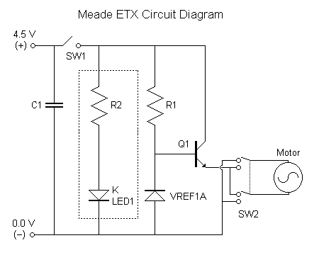
Note: if you have never soldered circuit boards before, you might NOT want to try this; at the very least, get some pointers from someone who HAS worked with circuit boards.
Parts needed: Low-current (2 mA) red LED; e.g. Radio Shack cat. #276-044; ~99 cents/pkg of 2.
5.6k-ohm resister; e.g. Radio Shack cat. #271-1125; ~49 cents/pkg of 5.
Approx. 16 cm. of 26 gauge stranded insulated wire; e.g. Radio Shack cat. #14-426-1H11; ~$2.00 for a small roll.
Electronics-grade solder; e.g. Radio Shack cat. #64-005; ~$2.50 for a large roll.
Glue, such as cyanoacrylate.
Tools needed: Large Phillips screwdriver
Small Phillips screwdriver
Soldering gun
Wire trimming shears
Electric drill
11/64" or 3/16" drill bit (assuming you are able to find the exact LED listed above)
Helpful accessories:
Small breadboard for testing LED
(1) Before opening the ETX base, cut your wire to length -- 2 pieces each about 6 - 8 cm. long -- then trim about a cm. of insulation off each end and solder one end of each wire to the LED leads. Test the LED with a couple batteries in series so that you know which lead should go to (+) and which to (-).
(2) Now open the bottom of the ETX base; remove the batteries, then remove the 4 small screws holding the circuit board in. Gently remove the circuit board, being careful not to damage the wires leading to the motor.
(3) On the circuit board you should be able to find a drawing of a resistor labelled "R2" with a hole at each end. Insert the leads of the 5.6k-ohm resistor through the holes, flip the board over, solder the resistor in place, and trim the excess lead-wire.
(4) You should be able to find a circle drawn on the circuit board labelled "K LED1." It will have two holes; flip the circuit board over and trace the connections; one of the holes will lead to the (-) battery terminal; the other will lead to the "R2" resistor. Insert the exposed free ends of the wires that you attached to the LED through the two holes, flip the board over, solder the wires in place, and trim the excess.
(5) Before going any further, I recommend replacing the batteries and testing your circuit by turning the drive on and off. If you have the LED in backwards, fix it now.
(6) You'll need a spot to place the LED so you can see it; it fits nicely into the unused latitude-adjustment leg aperture in the removable metal base-plate. It's not an easily visible location, but at least you don't have to drill into your ETX. I preferred to drill a hole in the side of the plastic base, opposite one of the legs and near one corner of the circuit board. There's no ideal spot, so pick your own, but PLAN AHEAD - make sure you don't end up drilling into one of the many struts supporting the inside of the base, and make sure your site has plenty of elbow room inside so you can wiggle the LED into position. If you use an 11/64" drill bit, you should be able to just force the LED snugly into position; if you use a 3/16" bit, you'll have a looser fit and will need a couple dabs of glue.
(7) Once the LED is in position, screw the circuit board back into place and close up the base; you're done. Good luck.
Mike here: Remember that this will invalidate any warranty on your ETX. Neither Paul nor myself are responsible for any modifications or damage that may result from making any modifications to your ETX.
From: Lawrence A. Ciscon (lciscon@capsela.modulus.com)
I wanted to add my appreciation for your fantastic web site on the ETX. I was thinking of buying one about a month ago, found your site & went for it largely based on the info at the site. I thought I would reciprocate with some information on my initial experiments with Eyepiece Projection photography I've made with a CCD camera.
 Based upon your experiences with the basic camera adapter & my own 5-minutes with it in the store, I decided that that approach wouldn't work very well for me. I wanted something that I could use for a variety of magnifications & combinations of eyepieces, barlows, etc. So I purchased a Celestron Deluxe Tele-Extender (#93643 I believe). This has the advantage of having a significantly larger diameter so that larger diameter eyepieces will fit within it, and it is long enough that a eyepiece and barlow combination fits inside it.
Now the trick was how to get it to attach to the eyepiece holder of the ETX. The Deluxe Tele-Extender includes two set-screws that are 90 degrees apart that are designed to tighten it against the outer rim of a SCT eyepiece holder. Furthermore it has a little protrusion where the set screw for the eypiece holder fits. Usually this whole assembly fits on the back of a larger SCT telescope, so the fact that these protrusions & screws stick out at all angles doesn't matter. But on the ETX, they hit the telescope case when you try to slide it down over the holder. My solution was to remove one of the screws. That gave it enough room to fit down all the way. It's pretty obvious which one to remove when you try to fit it on with the protrusion for the eyepiece holder set screw aligned correctly.
The next problem was that the end of the Extender was too large to fit snugly on the holder. I fixed this by taking one of the velcro cable-ties (they have the fuzzy stuff on one side and the hooks on the other...very useful) you can buy at Walgreens and just wrapping it around the eyepiece holder right at the telescope. You have to be careful to have only one thickness of this stuff on the side where there is very little clearance between the eyepiece holder and the plastic ring of the telescope a little farther up (otherwise the Extender won't fit between them). Now the Extender will simply slide over the velcro & form a nice snug fit against the tube. Voila!
Now you can put combinations of lenses and barlows on the eyepiece and simply slip the extender over the whole thing. It's important, though, that the eyepiece combination has to extend to the end of the Extender tube to get the right distance to the camera/CCD. For lower powers I achieved this by buying a 1" (or even 2" for a short eyepiece) eyepiece extension tube that I insert as if it were a barlow. This also works in conjunction with the short barlow, if necessary. Fine adjustments on the length can be made by pulling the barlow/extension out of the eyepiece holder a bit & tightening down the set screw to hold it at that length. In my initial experiments I've been able to get these combinations to focus properly without too much trouble (although I haven't tried all combos yet).
The CCD camera I'm using is a QuickCam II. At less than $200, I believe that this is a nice throw-away starter CCD for playing with this stuff. It has 24-bit color at 640x480 resolution and can take timed exposures of any duration (although It doesn't have controls for sub-second exposures). To mount this to the Extender, I used a simpler technique than that described by Paul Boudreaux. I removed the cover of the QuickCam using the standard techniques (see Paul's description), and unscrewed the standard lens that comes with it. Instead of building a new lens or tube, however, I just filed off the plastic ridge on the lens that holds it inside of the QuickCam ball. This allows me to remove & reattach the lens with the QuickCam reassembled, so I can look at the affects both ways (all pictures I have taken with it thus far I've actually left the lens on focused at infinite). Then I bought the smallest camera T- ring adaptor I could find (I just dug thru several boxes at my local astronomy store to find the smallest). I found one in which the thread portion could be removed to make it even smaller. Then I simply epoxied this onto the QuickCam ball aligned with the front lens. This is very solid & lets me still use the QuickCam for taking non-astronomy pictures. The whole QuickCam then screws onto the back of the Extender.
I've just started to play with this stuff (including the basics of Astronomy itself), but my initial impressions are that this combination works very well for lunar and planetary photography. I am still learning to locate deep-space objects in our heavily light-polluted area, so I don't have any feedback on that yet.
Hope this is useful
-larry
 From: Paul J. Boudreaux (boudreau@eng.umd.edu)
How I made the connection to the Meade T64 attachment for prime focus CCD photography with the Connectix Color QuickCam (~$220 for color, ~$99 for B/W) camera:
First I removed the cover from the QuickCam by using a bent paperclip to open the plastic latches that hold the two halves of the QuickCam together. There are actually three holes in the spherical case. The obvious one is in 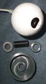 the rear right below the cable feed-thru. The other two are located in the front holes of the triangular hole array on each side of the sphere. After opening the camera, I removed the lens by unscrewing it from the plastic assembly. Later I removed the color balance filter. This is not necessary, but I did it. Using the same thread size, I fashioned a threaded hollow tube
  to screw into the plastic lens holder assembly over the CCD. Two round lock nuts thread onto this hollow outside threaded tube. Next I machined an endcap to fit to the Meade T64 T adapter. The T adapter screws onto the prime focus port of the ETX. This end cap was also threaded to fit the T64 T adapter and threaded in a center hole in the cap to match the outside threaded hollow tube now on the CCD camera. This assembly holds the CCD camera beatifully to the ETX.
 Of course, one could simply glue the camera to a cork or stiff foam plastic with a hole for the CCD aperture and push the cork (or plastic) into the end of the T64 T adapter or any such quick attach. I had access to shop tools, so I opted for the more sturdy mechanical approach.
I am quite pleased with the results. Both Astrophotography of the sun with sunspots and lunar photos are now very simple. The QuickCam software that runs on my laptop gives quick and easy exposures. I hope to next take images of the planets.
From: Han Kleijn (Han_Kleijn@compuserve.com)
 Several ETX users asked me how I made my pictures or how I adapt my camera to the ETX. To answer those questions I added a page in my web. In this short page I describe briefly my photo experiences and how I use the #64 T-Adapter. This adapter is in several countries standard supplied with ETX. It is intended for 'direct focus' pictures (see fig 11 in the manual) but can also be abused for eyepc projection. More information in my ourworld.compuserve.com/homepages/han_kleijn/makingph.htm web page.
From: Paul Boudreaux (boudreau@eng.umd.edu)
 Larry Janowicy's PVC 4 inch pipe connector idea for an inexpensive dew shield for the ETX appealed to me. For $0.75 I purchased one from a local Lowes store in Maryland. Using Flat Black paint with a self adhesive velcro tape, I made one in just a few minutes. It worked quite well on the first cool dewey evening in Maryland. I highly recommend it.
The digital photos show it attached to the ETX and also an oblique view showing the velcro tape that makes such a great snug fit to the ETX. I hope your readers can make use of these great ideas posted on your web site!
From: Han Kleijn (Han_Kleijn@compuserve.com)
Han has developed an excellent Excel 4 table (ourworld.compuserve.com/homepages/han_kleijn/exposure.zip) to calculate the film exposure times for the ETX and of course any other telescope. The latest version of this file is now available on Han's web page.
From: Han Kleijn (Han_Kleijn@compuserve.com)
I bought my ETX some weeks ago. The optics were fine but the RA speed was terrible wrong! With the motor running, a typical star went in 10 minutes out of sight. After carefully checking the polar alignment and monitoring the ETX RA-scale in a run of 12 hour, I found that the RA motor had an error of one hour in the 24 hours!!. I'm a beginning astronomer, but this was much more then acceptable and reported by the dealer (10 minutes in 24 hours and in the review of Sky & Telescope 1/97 the accuracy was even better!.)
The dealer offered me to take the ETX back and returning my money. He had no other ETX as replacement. This would mean that I had to wait 3 months or more for an other ETX. It would also mean a drive of 700 KM back to the dealer.
I can not understand that the quality control of MEADE can accept such an offset in the RA speed!! The dealer tested the telescope prior to selling it to me, but also he did not notice the big offset. In Europe the price of the ETX is about US $ 1000,- For such a price, I expect something which can keep a planet or star in sight for an half hour or so.
However giving the scope back, would mean for months no observing. To identify the problem, I did some measurement and decided to modify the scope electronics (and taking the risk). It worked out very well. By changing the 2,5 Volt reference diode from a fixed LM385 to an adjustable LM336 of 2,5 V, I'm now able to adjust the motor voltage and therefore the motor speed. The RA speed is now spot on. The resistor of 3k9 was changed to 2k2 and across the new reference diode a 22k potentiometer was connected. The arm of the potentiometer was connected to the adjust-gate of the new LM336. With this potentiometer the RA-speed can be adjusted plus or minus 7%.


I also tried a zener diode of 2,7 V. The voltage across a zener diode is however is varying to much with the current and therefore the battery voltage (some %). The result is a very unstable motor speed. and absolute not practical.
If you want to know more, my E-mail address is:
Han_Kleijn@compuserve.com Compuserve address: 100103,23
Han Kleijn, Date: 17-4-97
Mike here: this will most certainly void your ETX warranty. Exercise caution. Neither Han, myself, nor Meade can be responsible for any damage that may result from attempting this modification.
Return to the top of this page.
Go back to my ETX Home Page.