 |
Last updated: 27 August 2011 |
![[Home!]](../../images/mighty_etx_logo_orig-sm.jpg) |
|
Sent:	Wednesday, August 24, 2011 22:04:03
From:	Myers, Brad (myersbw@muohio.edu)
LOVE your ETX site.  I dove into it a couple years ago for the Autostar
info.  But, I recently purchased a 6-7 year old ETX90ec (uhtc coatings)
that I love and ended up repairing stripped gears in the RA assembly.
Well, between information on your site and others, I finally got brave
and did the repair myself.  Attached is an RTF file that documents the
repair with photos.   I hope this is something you can use on the site.

Thanks for creating the site and hosting such a wealth of info on these
little gems.

Cheers!
Brad
Well, I bought an ETX90ec on CL ran it through it's paces andooopsit refused to move in RA after about a minute of motion. There were some rather loud clicks reminiscent of popping plastic and, oh well, stripped gears. I scoured the net for resources. Purchasing a factory replacement gearbox was too pricey. And the resources were a bit scattered. Some info came through web searches in various places. Some was found on Weasner's wonderful site (especially if you're an ETX fan).
I did finally come across some information about replacement gears and thoughtalrightelectronic technology is my background, but heyit's now just manually guided tube unless I can resurrect it. Thanks be to GodI conquered it. It's now in working order. So, here's the pictorial account that it might help someone.
1 - With an allen (hex) head wrench, remove the four screws securing the ETX90 to the fork assembly. Once the screws are out, you'll need to brace and pull the forks slightly apart to allow he scope to slip out the back of the forks for removal (getting it out of your way to prevent damage).
2 - Flip the base unit over and remove the three rubber feet to reveal 3 screws which secure the bottom plate. (remove any batteries before removing the plate)
Now you see what's depicted below. The worm gear is to the right of centerand you'll see a large gear connected to the end of the worm gear (of which is also resting in the gearbox (black assembly).
3 - What you want to do here is remove the worm AND the gearbox together as one. The gearbox has 4 screws - PAY ATTENTION HERE :) - you want to remove the 2 screws at the extremes (they secure the gearbox to the base)LEAVE the two center-most screws for now. (These two hold the gearbox upper & lower halves together.)
4 - Remove the 3 screws securing the worm gear.
5 - Last, follow the wires from the gearbox motor and remove the connector from the circuit board (This is the only electrical connection you need to remove, but I snapped a pic before I started removing anything.)
The worm gear/gearbox will simply lift out.

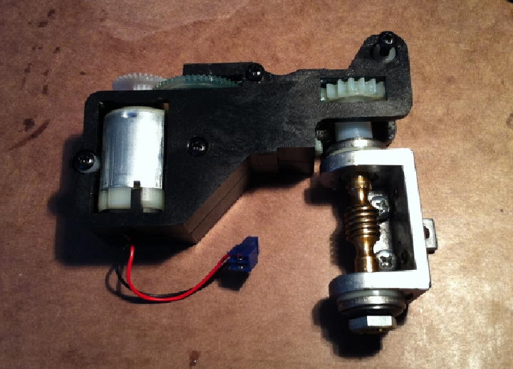
Here's the removed assembly. To work on the pieces, we need to separate the worm assembly. If you loosen the inner screw closet to the worm assembly, the gearbox top plate will lift up a little, allowing you to tilt the worm assembly up and remove it. (Loosen the other inner screw just a littlehalf turn or soif you have a difficult time getting the clearance you need.

Here are the two assemblies separated. The three silver screws are the worm assembly mounting screws.

Now's a good time to point out my issue with the worm assembly. Notice the massive gear at the end of the worm? That gear slides over a tapered shaft and is held in place by a small hex screw in the end of the shaft. The problem? That attaching point is VERY thin plastic. It didn't take much seizing and that end piece sheared off. Repairing this was make-or-break. If I couldn't fix itI'd almost double my investment in the scope with the price tag for a new part.
Here's my fixunorthodoxbut, it works! See the small metal head just at the end of that large gear? Well, it turns out that a good ole female DB9 connector post has the same thread size. (You'll recognize it as a typical pc's serial port 9 pin connector post.) But, my other issue was gripping power to the worm shaft itself.
My guess? I believe the assembly was originally tensioned so that it will serve as a clutch-style connection. After seeing the gearbox gutsdon't worry about restoring it. I wasn't going to be able to replicate thatand the gear that actually stripped?? Peanuts to replace and so simple. So, I cleaned it up and used common silicone caulk to lightly coat the worm shaft and adhere the end gear. Then, used the DB9 nut to pull in the gear and lightly tension the entire assembly.
A NOTE ABOUT TENSION: This got me the first go around. When that gear endpoint shearsthe whole worm works out of the assembly a bit. The larger nut on the right in the photo is already tightly securedleave it as-is if it hasn't broken loose. What you want to do is tighten the DB9 nut so that you draw it together with NO PLAYdo NOT tensionthe worm needs to freewheel as loose (without slop) as possibleno side-to-side play. Rotate the worm assembled to test, but spin the large nut to do so (especially if the silicone hasn't setup yet).
Now, I'll assume you have the worm gear in a repaired state. Set it aside for the moment.
On to the gearbox disassembly - :)
1 - Unscrew the inner two gearbox screws until you can lift off the top plate and set it aside. (photo below) All those gears you see just set freely on their shafts. In this picture, the stripped gear has already been removed (I pulled it a month ago when I placed the gear order.) But, do note all the lubricant. As others have noted, it's excessive. I took a dental pic and lightly scraped all the excess off. You don't need to clean the gearsjust scrape off all the excess. Also, notice there's a bit of extra lube that flung onto the side of the motorclean that up, too.

Gear Prep!
Here's a shot of the gearsguess which is the bad one. ;) The important measurement (tooth count & width) matched. Note the extra shaft length. I used a fresh razor knife to slice a couple mm off. I didn't measure. I eyeballed it. This is tough plastic! It won't cut easilyit sort of chipped. I cut from two sides of the shaft and used a jeweler's flat file to finish it. (A jeweler's saw might have worked a bit betterjust protect the gear teeth). You'll also find that the shaft hole is slightly undersized. One user noted a 3mm drill bit to widen it. Well, my local hardware store didn't stock metric sizes, but I found a 1/8" bit did ok. a hair too much, but works fine. As you'll be filing this a bitmake certain you thoroughly wash the gear off once you have it sized properly.

Gear Insertion TIme!
Here you see the new gear in place (yeah, yeahI still haven't cleaned my lube off yet!).
1 - Notice the gear attached to the motor. That large tooth area at the end of the shaft gear needs to be clean and free of debris (you'll see some in the pic). That's the encoder wheel the circuit uses to sync position. Debris in that will produce sync errors make the whole assembly erratic or altogether useless.

Worm Gear Mount Damage.
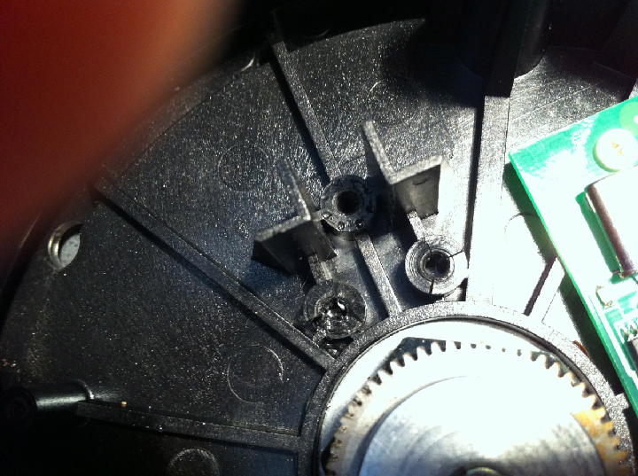
This picture may very well be showing the root cause of my problems. (But, I think the worm gear shearing and forcing the worm out the side of it's bushings is likely the real culprit for the fracturing.) Note the stress fractures around the screw holes for the worm mount. You can't see it well, but that top-most hole is also showing very slight splits. I'm guessing that, with heat, etc, the plastic is slowly disintegratingperhaps the oils evaporating leading to what most of us call "dry rot". Or, the screws might have been over-torqued at the factory? Who knows. But this was calling for a drastic fix. My remedy? Good ole JB Weld!

Repair Fabrication Started.
JB Weld comes in several versions. Temperature wasn't a concern, but I wanted a quicker fix, so I used their 7 minute version. It actually starts curing in about 4 minutes (work time). You're seeing this is mid-process. I'd mix a small amount upapply itmix a little morekeep building it up. Just go SLOWLY and avoid getting it down near that center nut assembly.
You can get pretty generous with this stuff. The idea is to reinforce the local structure. If the holes are all shotsimply fill them all inlet it cure for 4 hours and re-drill holes for the screws. It's tough stuff! :O
You can also see where I put some behind the large L-shaped supports, etc.

The Home Stretch...
At this point, it's a gentle reassemble, let it all setup overnightthen test. (The silicone, if used, will take the longest curing time.)
So, remember the step above for removing the worm gear? Reinstall it to the gearbox BEFORE you install back into the base. Also, save yourself a headachedrop in the 2 worm mounting screws NEXT to the worm before you install, too. Grab the gearbox in your left handthe worm in your rightand lower it into place.
Once installedremember the encoder wheel at the end of the motor? The gear just to the right of it can be hand-spun to test movement. About the worm..it needs to be a slop-free fitbut not tight. If you have to press much to set it incheck for worm or gear debrisif noneremove the assemblies and make sure you didn't get any epoxy on those positioning flats. If you did, a razor knife/exacto blade will scrape it off if you catch it before it sets up too hard. Re-insert the assemblies and tighten "just to", but not overly snug. (As we've learnedtension & plastic are opposing terms!)

That's All, Folks!
Pop the bottom plate back on. Again let it all set a full day before powering up (IF you had to do the worm repair). Else, 5-6 hours should be plenty.
Following is the link and info for the gears & distributor.
Gizmos, (http://www.gizmoszone.com) - Locate in Hong Kong, they delivered within their 2 week estimate and will take PayPal.
The first listed is the common one to strip, it drives the large gear on the worm shaft.
Worm-driving gear...
Quantity: 3 (DEFINITELY buy extras!)
Product: GS0.5-24-29
Options:
Cost (each): $2.10
Item Subtotal: $6.30 (As of July 2011)
This second one is one of a few of the same size compound gears in the train. The company has a $10 min and the least expensive shipping was $4.95. So, I figure a $15 fix with parts to spare was a wise way to approach it.
Compound gear in train....
Quantity: 2
Product: GC0.5-12/24-20
Options:
Cost (each): $2.30
Item Subtotal: $4.60
I hope this helps reduce the time of repairs for those of you that want to resurrect your own ETX scope. This base is certainly the weak link of the whole scope package. But, very repairable, given resources and a little patience. I'd estimate that I have a total of about 4-5 hours for the entire repair NOT including the research for resources, etc. Not very time-cost-effectivebut very rewarding to get it back in operation.
Clear Skies & God Bless,
Brad
Go back to the Tech Tips page.
Go back to the ETX Home Page.